| DSP Blockset | Search Help Desk |
| Filter Realization Wizard | Examples See Also |
Automatically construct filter realizations using Sum, Gain, and Unit Delay blocks.
Library
Filter Realizations, in FilteringDescription
The Filter Realization Wizard is a tool for automatically creating filter realizations with specific architectures. The Wizard's interface allows you to specify the filter's structure and coefficients, the type of data to be filtered, and optimization criteria for the design. The Wizard then builds the specified filter as a subsystem composed of Sum, Gain, and Unit Delay blocks. You can select the name of the subsystem ("Filter" is the default) and whether it is placed in the current model or in a new model. The Architecture panel in the Wizard's interface allows you to select from the following realizations.Fixed-Point Options
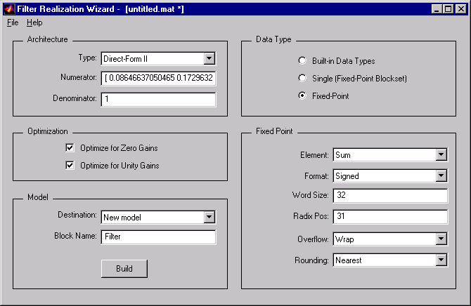
By default, the filter constructed by the Filter Realization Wizard operates using the Simulink standard double-precision arithmetic. If you have the Fixed-Point Blockset installed on your system, you have the additional option of building the filter to operate using single-precision or fixed-point arithmetic. Select the option you want from the Data Type panel.The filter is constructed from the standard Simulink Sum, Gain, and Unit Delay blocks, and operates in any precision supported by Simulink (e.g., double-precision, single-precision, Boolean, etc.). This is the default.
The filter is constructed from the FixPt Sum, FixPt Gain, and FixPt Unit Delay blocks from the Fixed-Point Blockset. The blocks are configured for single-precision arithmetic.
The filter is constructed from the FixPt Sum, FixPt Gain, and FixPt Unit Delay blocks from the Fixed-Point Blockset. The FixPt Sum and FixPt Gain blocks are configured for fixed-point arithmetic using the options specified in the Fixed-Point panel of the Filter Realization Wizard. These options include:
Dialog Box
The parameters displayed in the Architecture panel vary for different selections in the Type menu. Only a portion of the parameters listed below are visible in the wizard at any one time.
Examples
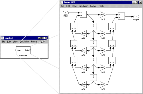
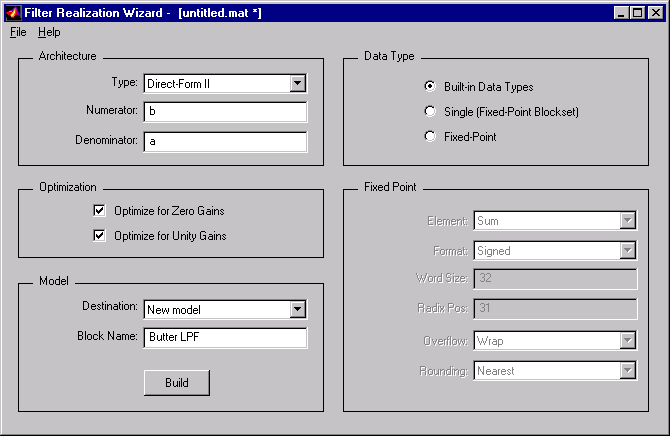
Example 1: Direct Form II
Design an fourth-order, quarter-band, lowpass Butterworth filter:[b,a] = butter(4,.25);
b and a as the numerator and denominator of a
Direct-Form II structure:
b in the Numerator text field.
a in the Denominator text field.
Butter LPF.
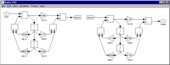
Example 2: Second Order Sections
Design an eighth-order, quarter-band, lowpass Butterworth filter using second-order sections (SOS):[a,b,c,d] = butter(4,.25); sos = ss2sos(a,b,c,d);
sos as the numerator of a Direct-Form II
structure:
sos in the Numerator text field.
Butter SOS.
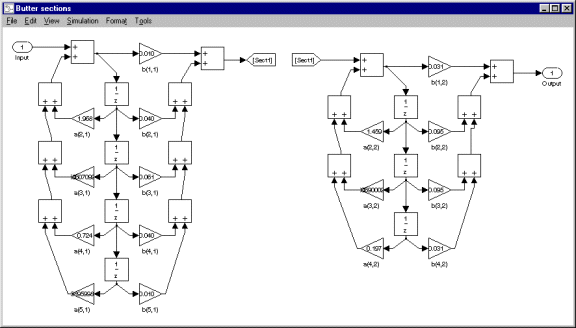
Example 3: Nth Order Sections
Design a lowpass Butterworth filter using Nth order cascades:[b1,a1] = butter(4,.25); [b2,a2] = butter(3,.25);
{b1,b2} in the Numerator text field. Note that the numerator coefficient vector for each section is entered as an element in a cell array. Since this is a two-section filter, a two-cell array is specified in the Numerator field. The two filter sections do not need to have the same order.
{a1,a2} in the Denominator text field. Note that the denominator coefficient vector for each section is also entered as an element in a cell array. Since this is a two-section filter, a two-cell array is specified in the Denominator field.
Butter sections.
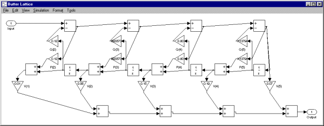
Example 4: ARMA Lattice
Design a fourth-order, quarter-band, lowpass Butterworth filter using an ARMA lattice:k and v, respectively) for the ARMA filter:
[b,a] = butter(4,.25);
[k,v] = tf2latc(b,a);
k and v as the coefficients of the lattice design:
k in the Lattice Coeffs text field.
v in the Ladder Coeffs text field.
Butter Lattice.
References
Oppenheim, A. V. and R. W. Schafer. Discrete-Time Signal Processing. Englewood Cliffs, NJ: Prentice Hall, 1989. Proakis, J. and D. Manolakis. Digital Signal Processing. 3rd ed. Englewood Cliffs, NJ: Prentice-Hall, 1996.See Also
Biquadratic Filter