| Power System Blockset | Search Help Desk |
| Asynchronous Machine | Examples |
Model the dynamics of a three-phase asynchronous machine
Library
Machines LibraryDescription
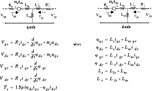
 : stator q and d axis fluxes
 : rotor q and d axis fluxes
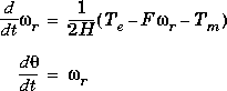
 : angular velocity of the rotor
 : electrical angular velocity (
 )
)
 : rotor angular position
Parameters and Dialog Boxes
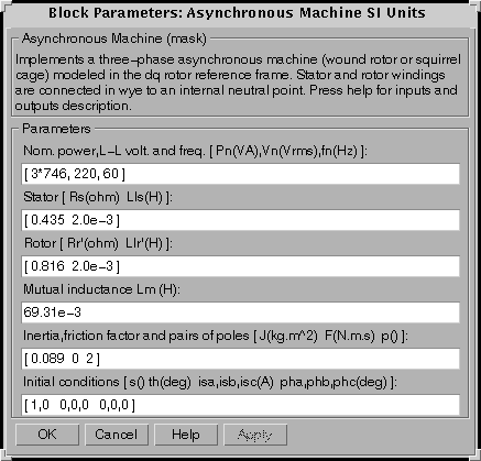
In the powerlib library you can choose between two Asynchronous Machine blocks to specify the electrical and mechanical parameters of the model. S.I. Units Dialog BoxIf you choose to enter the parameters in S.I. units, you must first enter the nominal power (VA), line-to-line rms voltage (V) and frequency (Hz). The second entry is the stator resistance (ohm) and leakage inductance (H). The third entry is the rotor resistance (ohm) and leakage inductance (H), both viewed from the stator. The fourth entry is the mutual inductance (H). The fifth entry is the inertia (kg.m2), the viscous friction coefficient (N.m.s) and the number of pole pairs. Finally, the sixth entry is where you specify initial slip, electrical angle (degrees) and stator currents (magnitude in A, phase angle in degrees).
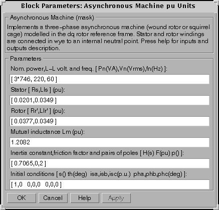
Per Unit (pu) Dialog BoxIf you choose to enter the parameters in per unit, you must enter at the first line the nominal power (VA), line-to-line rms voltage (V) and frequency (Hz). You then enter the electrical and mechanical parameters expressed in pu, with the exception of H, which is expressed in s. Initial conditions are entered the same way as in the S.I. units case, except that the current magnitudes are in pu.
Note: These two blocks simulate the same asynchronous machine model. The only difference is that the parameters are expressed in different units.Inputs and Outputs
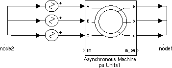
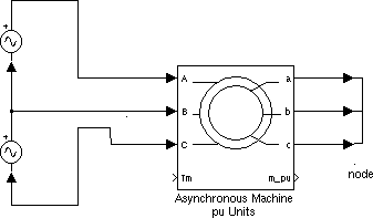
The electrical inputs of the block are the three electrical connections of the stator, and the electrical outputs are the three electrical connections of the rotor. Note that the neutral connections of the stator and rotor windings are not available; three-wire Y connections are assumed. The rotor's connections should ordinarily be short-circuited or connected to an external circuit, for example external resistors or a power converter. You must be careful when you connect ideal sources to the machine's stator. If you choose to supply the stator via a three-phase Y-connected infinite voltage source, you must use three sources connected in Y.However, if you choose to simulate a source delta connection, you must only use two sources connected in series:
The Simulink input of the block is the mechanical torque at the machine's shaft. This input must be positive in the motoring mode and negative in the generating mode.
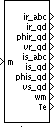
The Simulink output of the block is a vector containing 20 variables. They are, in order (refer to "Description" section, all currents flowing into machine): 'qr,
'qr,  'dr, v'qr and v'dr
 qs,
qs,  ds, vqs and vds;
 and Te
Limitations
The Asynchronous Machine block does not include a representation of the effects of stator and rotor iron saturation.Example
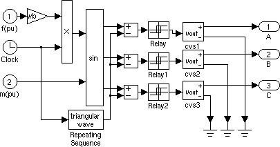
This example illustrates the use of the Asynchronous Machine block in motoring mode. It consists of an asynchronous machine in an open-loop speed control system. The machine's rotor is short-circuited and the stator is fed by a PWM inverter, which is built with Simulink blocks and interfaced to the Asynchronous Machine block through the Controlled Voltage Source blocks. The inverter uses sinusoidal pulse-width modulation, which is described in [1]. The base frequency of the sinusoidal reference wave is set at 60 Hz and the triangular carrier wave's frequency is set at 360 Hz. The 3 HP machine is connected to a constant load of nominal value (11.87 N.m). It is started and reaches the setpoint speed of 0.5 pu at t=1.0 second, at which time the setpoint is stepped to 0.75 pu. The parameters of the machine are those found in the SI dialog box.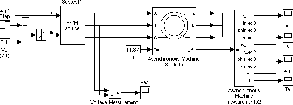
Open the Simulink diagram by typing psbpwm, or by double clicking on Asynchronous Machine (sim) in the demos library of powerlib. Set the simulation parameters as follows:
Stiff, ode15s
1.75 s
1e-4 and 1e-8, respectively.
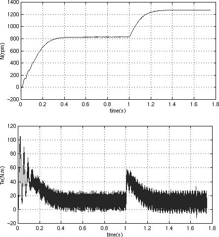
The top graph shows the machine's speed going from 0 to 810 rpm (0.5 pu) and then to 1252 rpm (0.75 pu). The bottom graph shows the electromagnetic torque developed by the machine. Since the stator is fed by a PWM inverter, a noisy torque is observed.
This noise is not visible in the speed however because it is filtered out by the machine's inertia, but it can also be seen in the stator and rotor currents, which are observed next.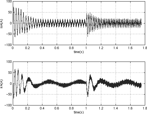
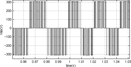
Finally, look at the output of the PWM inverter. Because nothing of interest can be seen at the simulation time scale, the graph concentrates on the moments preceding and following the speed step (around 1 second).
References
[1] Dubey G.K., Power Semiconductor Controlled Drives, section 8.1.4, Prentice-Hall, Inc., 1989.