Using Simulink     Search    Help Desk 
Selector

Select input elements.

Library

Signals & Systems

Description

The Selector block generates as output selective elements of the input vector.

The Elements parameter defines the order of the input vector elements in the output vector. The parameter must be specified as a vector unless only one element is being selected. For example, this model shows the Selector block icon and the output for an input vector of 
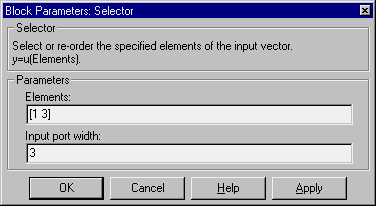
[2 4 6 8 10] and an Elements parameter value of [5 1 3].
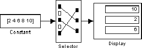

The block icon displays the ordering of input vector elements graphically. If the block is not large enough, it displays the block name.

The Selector block accepts signals of any signal and data type, including mixed-type signal vectors. The elements of the output vector have the same type as the corresponding selected input elements.

Data Type Support

A Selector block accepts and outputs signals of any numeric type (real or complex) and data type.

Parameters and Dialog Box

Elements
The order that the input elements are to appear in the output vector.
Input port width
The number of elements in the input vector.

Characteristics

Sample Time
Inherited from driving block
Vectorized
Yes


[ Previous | Help Desk | Next ]