| Using Simulink | Search Help Desk |
Signal Labels
You can label signals to annotate your model. Labels can appear above or below horizontal lines or line segments, and left or right of vertical lines or line segments. Labels can appear at either end, at the center, or in any combination of these locations.Using Signal Labels
To create a signal label, double-click on the line segment and type the label at the insertion point. When you click on another part of the model, the label fixes its location. NoteSignal Label Propagation
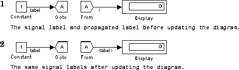
Signal label propagation is the automatic labeling of a line emitting from a connection block. Blocks that support signal label propagation are the Demux, Enable, From, Inport, Mux, Selector, and Subsystem blocks. The labeled signal must be on a line feeding a connecting block and the propagated signal must be on a line coming from the same connecting block or one associated with it. To propagate a signal label, create a signal label starting with the "<" character on the output of one of the listed connection blocks. When you run the simulation or update the diagram, the actual signal label appears, enclosed within angle brackets. The actual signal label is obtained by tracing back through the connection blocks until a signal label is encountered. This example shows a model with a signal label and the propagated label both before and after updating the block diagram. In the first figure, the signal entering the Goto block is labeledlabel and the signal leaving the associated From block is labeled with a single <. The second figure shows the same model after choosing Update Diagram from the Edit menu.