(Much of the next set of pages [until AVIRIS is discussed] has been condensed and reworded from a thorough review by Dr. Roger N. Clark of the U.S. Geological Survey, entitled Spectroscopy of Rocks and Minerals, and Principles of Spectroscopy, which can be accessed in its entirety at a site on the Internet. Most of the illustrations accompanying this summary were taken from that source.)
Spectroscopy is the science of measuring the spectral distribution of photon energies (as wavelengths or frequencies) associated with radiation that may be variably transmitted, reflected, emitted, or absorbed upon passing from one medium (vacuum; air) to another (material objects). Imaging spectroscopy is the special case in which spectral characteristics and variations as one variable can be tied to two additional variables, the spatial dimensions given by x and y positions, to generate color composite images (pictures), ratio and principal components images, and classification maps; in particular, images that represent the effects of diagnostic absorption bands can be produced to show specific spatial variability of certain material features that are discretely identified by one or more such bands.
When illumination (either polychromatic, like sunlight, or monochromatic, such as a laser beam) strikes a material, this electromagnetic radiation will likely be partitioned into one or more components that behave differently. Some of the radiation will be directly reflected. If the material is transparent, the bulk of the radiation will pass through but undergo a change in direction according to the differences in indices of refraction between the material(s) and the external medium (usually air; or water). If the material is translucent or, more commonly, opaque, fractions (wavelength-variable) of the radiation may penetrate, its rays undergoing refraction, but some will ultimately be reflected. Of the fraction absorbed, that radiation, to some degree, will be converted to heat so that the temperature of the object will rise causing an increase in emission detectable as thermal radiation.
If the material is granular or polycrystalline, light that is reflected will strike a number of surfaces (associated with grain or crystal boundaries), meeting individual surfaces at different angles of incidence and thus scattering the radiation at different angles. The light may actually bounce around or back and forth from several such surfaces before finally leaving as scattered beams. If the object's surface is smooth, a significant fraction is reflected as from a mirror, at an angle related to the angle of incidence. But, most surfaces tend towards some degree of roughness, so that the percentage or proportion of light reflected directly to the observer (an eye or an instrument) will be notably reduced. The degree of scattering is also controlled by the fraction of radiation that is absorbed.
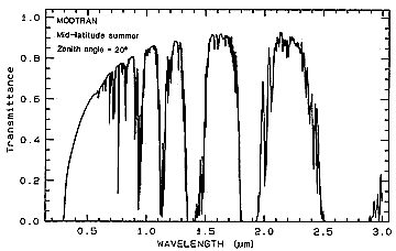
For a medium such as air, which also contains CO2 and other gases, water
(usually as vapor or tiny droplets), and particulates, some scattering occurs (hence blue skies
[high degree of scattering at blue wavelengths] and red sunsets [additional scattering at longer
wavelengths, leaving the red radiation less affected, i.e., transmitted as red). But, the bulk of
the radiation is either transmitted or absorbed, as indicated by this figure, with most of the minima
(absorption bands) due to the presence of carbon dioxide, water, and oxygen.

In the Visible-NIR range, water ice and dry ice (solid CO2) give characteristic spectral curves, as shown here:
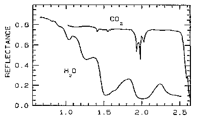
While moderate to high reflectances are necessary to produce the light tones in pictorial images, the wavelength-dependent absorption bands are the features in a spectral plot that commonly aid in identification of the materials that have bands (narrow to broad) that center at specific wavelengths. In the visible, the observed color(s) is likewise controlled by the relative values in the spectral curve that determine which wavelengths are reflected. Thus, a bright green color of an opaque material implies strong reflectance at green wavelengths and near total absorptance in the reds and blues; if instead there was also notable red reflectance, yellows to oranges would be the result. An absorbing medium affects the intensity of incoming radiation according to Beer's Law:
where I0 is the intensity of the incident radiation, e is the natural log, k = a constant that depends on absorption as a function of the complex index of refraction (which takes into account the role of the extinction coefficient K), and x = the depth of penetration. The bandwidth and depth of any given absorption depends on many different factors, one of which is the spectral composition of the illumination.
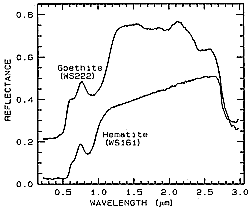
To illustrate how absorption bands plus reflectance levels can be used to distinguish
chemically similar materials, we will now look at the spectra for two minerals - Hematite
(Fe2O3) and Goethite (FeOOH). The first spectral curves
(obtained with a spectrometer in a laboratory environment) cover the spectral intervals (ranges)
between 0.3 and 1.0 µm (VNIR, for Visible and Near-InfraRed) and 1.0 to 2.5 µm
(SWIR, for ShortWaveInfraRed).
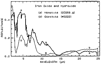
Here there is no offset, so the overall reflectance of Hematite is greater. Note the dual narrow absorption bands for Hematite around 3 µm. A paired absorption band for Goethite near 6 µm is distinct from the single band for Hematite at 7 µm. At longer wavelengths, including two in the 8-14 µm interval available to thermal sensors, Hematite shows several shallow absorption bands (sometimes also called "troughs" as contrasted to "peaks"). As we shall see later with several more examples, these MIR spectra can contain varied and definitive absorption features of considerable utility in distinguishing both between and within classes of materials. Unfortunately, no fine resolution instrument like AVIRIS (operating between 0.4 and 2.5 µm) has yet been developed for air/space platform use.
One more example emphasizes the power of detailed spectra in discrimination of similar related materials. (Offset; i.e., scaled) curves covering a portion of the SWIR range are presented for several minerals in the Kaolinite family of clays.
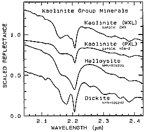
WXL refers to well-crystalized; PXL to poorly-crystallized. Although the gross expression of the absorption features is very similar among the four samples, slight shifts in the absorption band near 2.2 µm and other fine structure suggest that under exceptional circumstances these members of this clay group could be distinguished (but only with difficulty by AVIRIS).
Absorption bands play a key role in defining the spectra curves for organic matter such as vegetation. Consider this general curve (lighter line width) depicting the VNIR spectrum for a healthy oak leaf.
At longer wavelengths absorption by pigments and cellular matter are characteristic. Water bands also have a notable effect. Chlorophyll absorption dominates in the visible, removing both red and blue reflectances, leaving green as the dominant spectral wave range. The sharp rise in reflectance at 0.7 µm, continuing well beyond 1.1 µm, is largely the result of light being reflected by the walls of multiple cells. The second curve, rendered in heavier line weight, describes the spectrum of an oak leaf that is now dried and brown.
The next illustration shows four spectral curves, each for a particular vegetation type, and each of the upper three offset by 0.05 units from the one below. In general, these plots are nearly identical, with variations mainly in the depths of individual absorption bands.
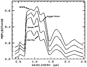
Although difficult for the eye to detect and distinguish, there are real differences in equivalent absorption bands that allow separations to be made. The absorption band at 0.7 µm is a case in point. Special processing is needed to single out small differences.
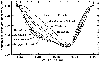
A procedure that facilitates making this distinction is known as continuum-removal. The continuum consists of the so-called "background absorption" which is in essence an extrapolation of the baseline of the general curve (fits a smoothed curve to the general trend so as to extend across the base of absorption bands). This local reduction specifies the continuum and is determined by mathematic manipulation of absorption coefficients by a subtraction process.
The depth of an absorption band, D, is given by:
where Rb is the reflectance at the bottom (trough center point) of a band and Rc is the continuum base.
The result for the above four vegetation plots (and several other crop types) is a set of continuum-removal curves that show slight to moderate differences in relative reflectances at a minimum centered on 0.68 µm. At least four of these crops appear distinguishable by their separations in the 0.56 to 0.66 µm interval.
The technique can work particularly well in picking out diagnostic bands for minerals that are very similar in crystal structure but differ in substitution of one chemical element (usually as an ion) for another. The common minerals Calcite (CaCO3) and Dolomite (Ca,MgCO3) have a prominent absorption band near 2.3 µm which achieves about the same depth in spectra of each species. The continuum-removal diagram for both shows that Dolomite reaches its trough point at a slightly lower wavelength.
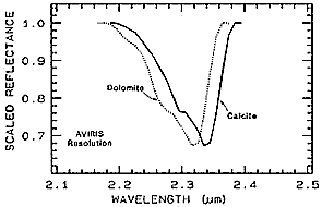
This approach to absorption band analysis has proved to be a powerful tool for enhancement and separation of small but often significant differences that allow materials (both those belonging to related groups and those unrelated but with absorption bands that tend to coincide) to be properly identified.
Code 935, Goddard Space Flight Center, NASA
Written by: Nicholas M. Short, Sr. email: nmshort@epix.net
and
Jon Robinson email: Jon.W.Robinson.1@gsfc.nasa.gov
Webmaster: Bill Dickinson Jr. email: rstwebmaster@gsti.com
Web Production: Christiane Robinson, Terri Ho and Nannette Fekete
Updated: 1999.03.15.