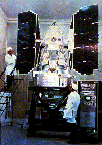
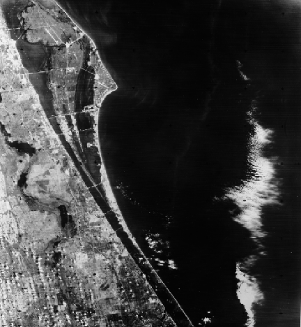
Renamed Landsat, this series of earth-observing satellites has permitted continuous coverage of most of the Earth's surface since then, with Landsat-5 currently still in operation. Other sensor/spacecraft systems have since joined this group, most notably the French SPOT (Système Probatoire d'Observation de la Terre) 3 band system.The first two Landsats supported two sensor systems. The RBV (Return Beam Vidicon) consisted of three TV-like cameras which used color filters to provide multispectral bands centered in the blue-green, yellow-red, and red-IR. This sensor failed early on the first ERTS and never came into routine use (a four camera RBV on Landsat-3 was a panchromatic [0.505 - 0.750 µm] version that provided four contiguous images at 30 m [79 ft] resolution). This RBV scene shows Cape Canaveral, where the Space Shuttle and other manned missions such as Apollo are launched.
The other instrument is the MSS (Multi-Spectral Scanner) that has operated on all Landsat spacecraft. A simplified model of this optical-mechanical sensor appears in the next figure.
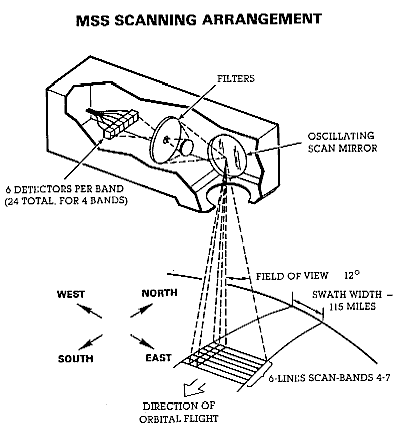
Light is gathered through a ground-pointing telescope (not shown). The scan mirror oscillates back and forth over an angular displacement of ± 2.89 degrees producing a beam width of 11.56 degrees that from an orbital altitude of 917 km (~570 miles) "sees" a swath width (Angular Field of View or AFOV) across the orbital track of 185 km (115 miles). During a forward scan, which takes about 3.3 milliseconds, a ground strip of ~ 474 m (1540 ft) is swept from one side of the track to the other. Reflected light gathered by this scan is passed through an optical train during which it is partitioned through 4 filters that produce spectral bands at 0.5 - 0.6 µm (green), 0.6 - 0.7 µm (red), 0.7 - 0.8 µm (photo-IR), and 0.8 - 1.1 µm (near-IR). Light through each filter reaches its set of six electronic detectors (24 in all) that subdivide the cross-track scan into 6 parallel lines, each equivalent to a ground width of 79 m (259 ft). The mirror movement rate is such that, at the orbital speed of 26690 kph (16680 mph), after the return oscillation the next forward swing produces a new path of 6 lines (79 x 6 = 474 m) just sidelapping the previous group of 6 lines.
Code 935, Goddard Space Flight Center, NASA
Written by: Nicholas M. Short, Sr. email: nmshort@epix.net
and
Jon Robinson email: Jon.W.Robinson.1@gsfc.nasa.gov
Webmaster: Bill Dickinson Jr. email: rstwebmaster@gsti.com
Web Production: Christiane Robinson, Terri Ho and Nannette Fekete
Updated: 1999.03.15.